Reviving A 117-Year-Old Concealed Carry Revolver
New Life For An H&R Safety Concealed Carry Revolver
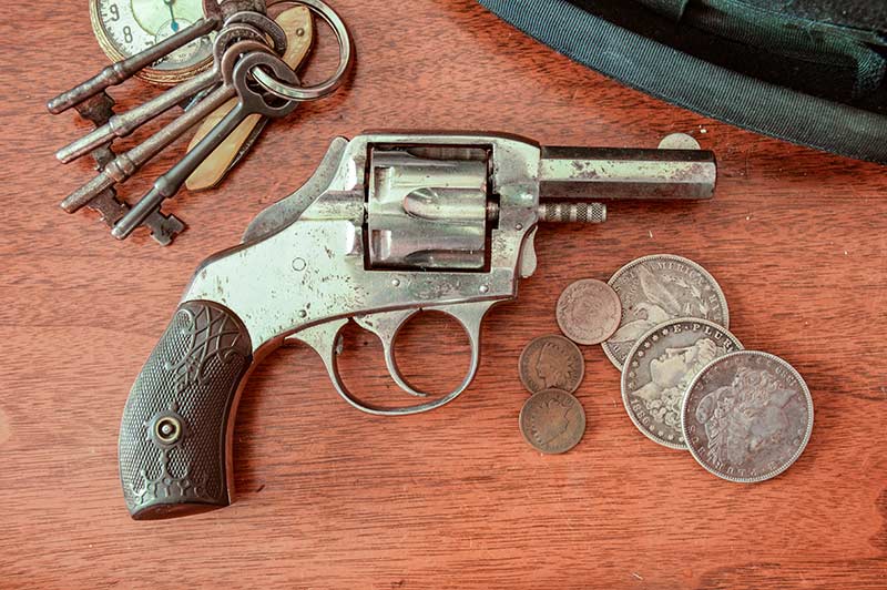
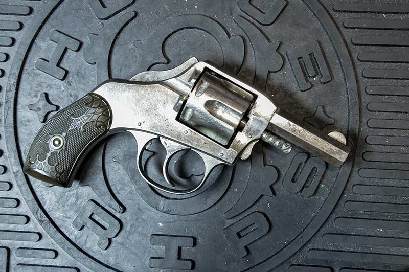
This H&R Safety Hammer double-action concealed carry revolver
likely has some stories to tell but needs some attention.

The spare parts from this 1940 Stoeger catalog are no longer available,
but you can find what you need at Numrich Arms.
Nothing quite removes anxiety over a gunsmithing project than working on an inexpensive firearm. Such is the case with my 117-year-old Harrington & Richardson Safety Hammer Double-Action Revolver. This was the concealed carry version of H&R’s American Double Action, one of America’s most popular handguns you’ve probably never heard of. Production began in 1884, ended during World War II and spanned the black and smokeless powder eras. H&R made over 850,000 American Doubles, mostly in .32 and .38 calibers. They cost a little over a dollar through the early 20th century, putting them within reach of working people looking for a reliable, easy-to-shoot and decently made weapon for self-defense.
There are still quite a few of these little guns around today, looking modest and unimpressive under gunshop glass next to their bigger, sexier and costlier 19th century Colt and Smith & Wesson peers. You can spot the Old West black powder models easily because those guns never had markings on the barrels.
In the case of my Safety Hammer model, the 1887 patent date on the hammer was a good clue, too. Retail price for a decent-looking functional gun is around $100 — less if they don’t work. I think it’s amazing for a gun that might have been in a riverboat gambler’s vest, an El Paso soiled-dove’s petticoat or a St. Louis wagon driver’s jacket pocket. The American Double Actions are rich in history but poor in modern collector appeal.
Use a bit of penetrating oil and let it sit for 30 minutes before trying to remove old pins.
Shooting Challenges
I enjoy shooting mine now and then with black powder loads and can attest it will hold its own at short range. The .32 caliber’s mild recoil makes it very easy to control in fast double-action shooting. Alas, nothing lasts forever, and the cumulative wear of a century resulted in two problems sidelining my gun for repairs.
The first problem became acute gradually. The primer in my low-powered black powder handloads at times backed out of the case during firing and jammed the cylinder against the recoil shield. This didn’t happen with original (vintage black powder) cartridges from some reason. I could minimize the primer protrusion on my ammunition, but the problem persisted. My conclusion was the depression in the recoil shield around the firing pin hole had finally gotten deep enough to anchor a fired case with even the slightest primer protrusion.
The second problem announced itself abruptly when the trigger failed to return forward after a double-action pull.
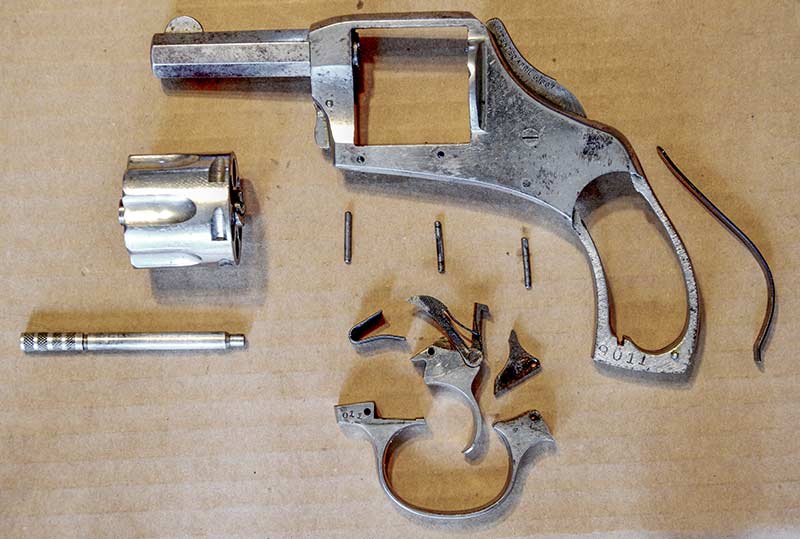
It’s a simple design, but parts are still easy to lose, so be careful.
Cost Effective Guns — And Fixes
Fortunately, both common problems have cost-effective solutions. Numrich Arms carries plenty of parts for old H&Rs, including modern replacement trigger-return springs. My cost, delivered, was less than $10. The primer-grabbing, action-jamming dent in my recoil shield required some thought and minor metal working, but no capital outlay. During the repair
process, I gained some insight, and a greater level of respect, for the production practices H&R used to make these guns. The company provided solid quality for the money.
The American Double Action pistols were designed for economy and efficiency of manufacture. Their one-piece solid frames were cast from malleable iron, with the interior cavities already in place. There are only two screws in the whole gun: One holds on the grips and the other provides the pivot point for the hammer. The barrel is threaded into the frame, but everything else is pinned in.
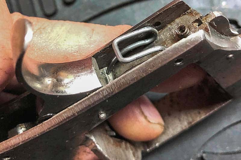
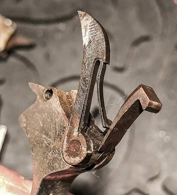
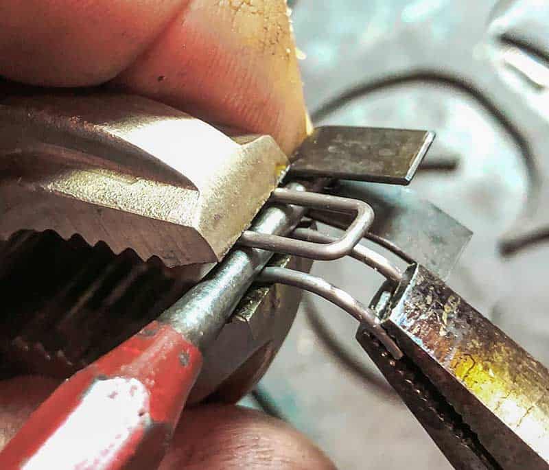
Note the feet of the replacement spring seated on the sharp flange of the trigger.
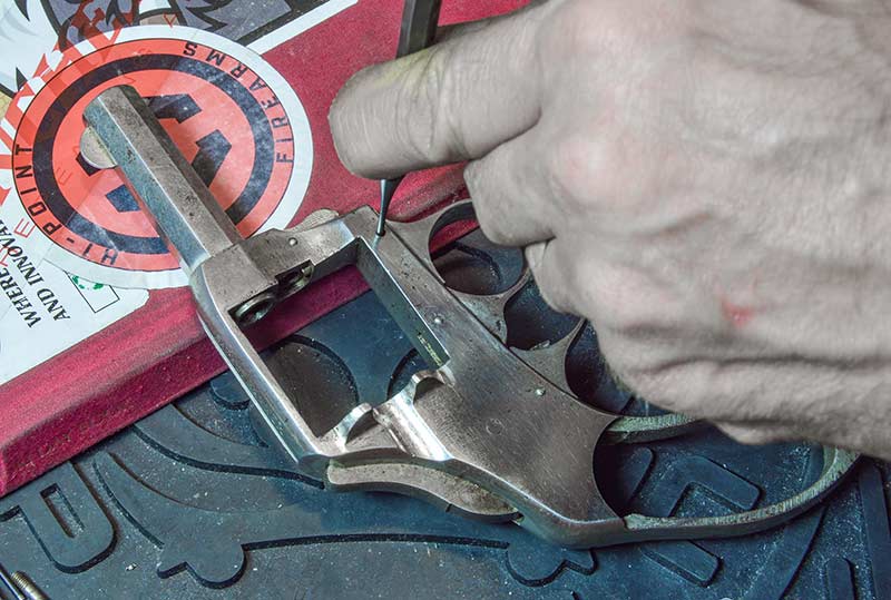
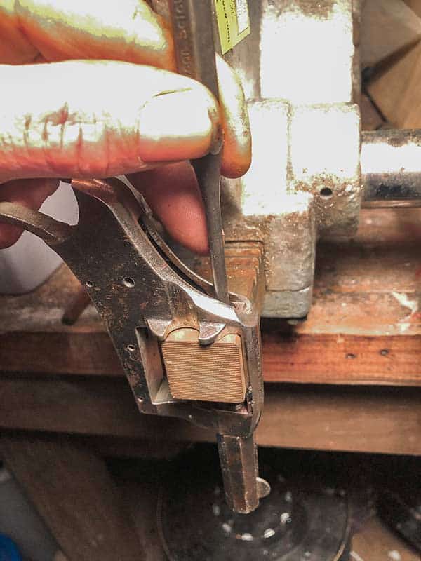
Frank is removing the mainspring so he can get the hammer out of the way.
Preparation
These guns don’t have a lot of parts, but try not to make the project bigger than it needs to be by carelessly losing or breaking them. Prepare your work area so little pieces don’t roll off into oblivion.
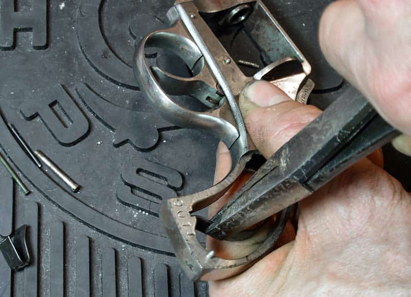
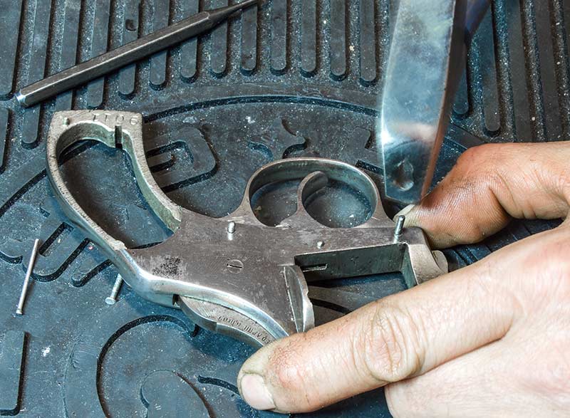
To replace the trigger-return spring, only the trigger guard needs to come off and it’s held on with just two pins directly above the front and rear legs of the guard. Since I also planned to repair the depression in the recoil shield around the firing pin hole, I needed to go further and empty the frame from the trigger backward. This included unpinning the trigger, hand and lifter assembly and removing the mainspring and hammer.
The grips are an old-fashioned Bakelite-type hard plastic that is brittle and prone to chipping. Use great care in removing them. They are held in the correct position by a pin through the bottom rear of the grip frame. This plastic doesn’t flex, so gently wiggle them off the pin with a razor blade or some other thin, broad object. A screwdriver tip is too thick for this job. Once you have the grips off, put them out of harm’s way so you don’t drop and break them. If they are already broken, you can get new replacements from Vintage Gun Grips for less than $20 plus shipping. They have a vast mold collection and are an excellent resource for rare grips.

Frank is using a Real Avid hollow-ground gunsmith screwdriver
to remove the hammer pivot screw without damage.
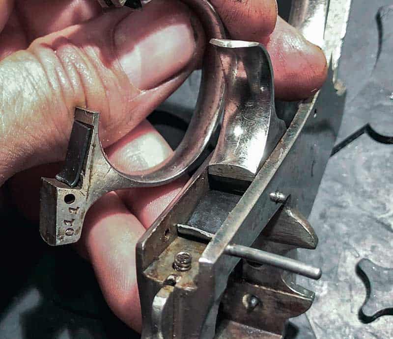
The correct trigger parts orientation.
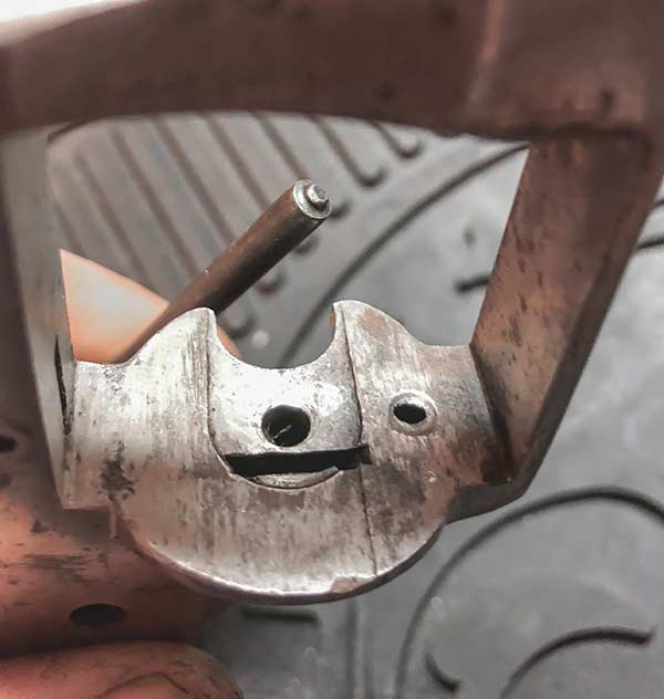
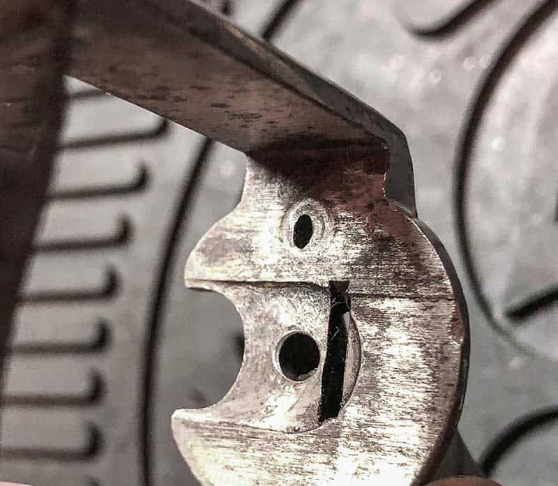
Note the dent in the recoil shield around the firing-pin hole.
It was causing periodic lockups when primers backed out.
Pin Removal
If the pin heads aren’t too heavily burred over, you can get them out easily. Prep them with a drop of penetrating oil and let it work its way in for half an hour before you start. Support the backside of the frame with some non-finish marring material (like the cover of my journal in this case), tap the pins flush against the frame with a brass drift and then drive them all the way out with a 1/16″ punch. You can make an expedient brass drift by slipping a spent .22 LR casing over the tip of a standard carpentry flat-point nail punch.
The pins are straight, not tapered, so they can go in and out in either direction. Tap in the side that looks like it’s small enough to pass through the hole without swaging. The iron is soft, and the pins are tiny, so they should yield with light hammer taps. Lay the pins aside so you know which one went where. Keep track of the left and right ends by making a pen mark on the right side of each pin and tape them to a piece of paper with a notation showing the proper hole.
With the front and rear retaining pins out, the trigger guard will drop from its milled slot on the bottom of the frame. The sear and tiny sear coil spring beneath it in the rear leg can fall free. The broken flat trigger-return spring and the tiny cylinder pin latch coil spring in the front of the trigger guard slot may also fall out. If those tiny coil springs don’t fall out, take them out immediately so they don’t get lost.
Save the broken trigger-return spring! Clean off the two halves and use some super glue to restore it to its original form so it can serve as a model for forming the replacement part. I needed a magnifying glass to get the edges of the break squared.
The culprit — a broken trigger-return spring.
Frank is using the old spring as a guide to replicate the overall spring height of the replacement part.
Adjusting The New Spring
Comparing the new wire trigger- return spring to the original flat spring, you’ll notice the wire spring looks too big to fit. That’s because it is. As delivered, it’s too tall and too long, so don’t try to force it. Compare it to your glued-up original spring and make the adjustment to overall height at the bend and the length of the legs. I squeezed the height of the bend down with a punch as a mandrel and a pair of vice grips. Naturally, this collapsed the feet of the legs of spring too, rendering it a lot less “springy.” While I had it in the vice grip jaws, I used pliers to flex the legs up evenly and restore their range of travel. You might have to do this a couple times until you get the overall height of the spring low enough to install the trigger guard.
Once you have the right spring height, refer again to the original spring and trim the legs of the wire spring to the same length. The ends of the legs are supposed to sit directly on top of the sharp leading edge of the trigger. You can fit the spring in with the legs too long, but if they extend too far over the sharp edge, they’ll lever upward off it when the trigger is pulled and jam its rearward motion. Trim with side cutters and then smooth the ends off with a Swiss file so they don’t abrade the trigger — the spring is harder metal than the trigger. The forward trigger guard retaining pin hole proved a good reference point for determining the correct spring length. When the bend of the spring came up to the near edge of the front trigger guard pin hole, with its legs sitting on the trigger’s leading edge, function was good. Get there and you’re ready to put it back together.
Anchor the trigger guard by partially setting the pins, then drive them all the way into position.
Reassembly
To prepare the frame and trigger guard for reassembly, start by reinstalling the tiny coil springs in their bores. I put a little grease in the hole to hold them in place better. The sear at the rear leg of the trigger guard is held in by the rear pin, so you need to make a slave pin to hold it in place temporarily. My slave pin was the point of a small finishing nail filed smooth so it wouldn’t drag in the hole. Finally, pre-insert the tips of your pins in their respective frame holes.
Now here’s the tricky part that’s easier with an assistant third hand. While holding the frame vertical, place the trigger-return spring in the frame with its legs on the trigger’s leading edge, and then press the trigger guard and sear assembly straight down into position. When it seats in the frame slot, try to push the pins in enough to engage its holes and keep it from popping out.
Then you can turn the gun on its side and tap the pins in until they are fully through the frame. The ends of the pins will stick out a little on each side of the frame. Use pliers to reinstall the mainspring — rounded end under the ledge on the bottom of the hammer — and test the trigger pull. If you adjusted the spring correctly, the trigger should return forward smartly after the hammer falls.
Sometimes a hammer is the right tool for the job. Note how Frank is
using the ram of his arbor press to back up the recoil shield face.
While it still shows its age and hard-earned wisdom, the recoil shield is now fully functional again.
Repairing The Recoil Shield
As my gun needed further disassembly to fix the dent in the recoil shield, there was no point in putting it all back together just yet. I needed to remove the trigger/hand/lifter assembly and hammer from the frame so I could use punches to drive out the dent from inside the firing-pin hole.
The hammer/hand/lifter assembly is held in by the same pin it pivots on. Remove it by driving out the pin and slipping a punch or some other slender object — like a straightened paper clip — behind the assembly to depress the lifter and hand spring and unhook the lifter from the notch on the hammer. Then you can pull the whole assembly out complete. Getting the hammer out requires removing its pivot screw.
Old screws can be a challenge to get out. Penetrating oil helps, but you’ll need a quality gunsmith screwdriver set with hollow ground bits of varying sizes to remove tight screws without damage. The Real Avid Smart Drive 90 set has nine widths of bits, and all the Torx and metric and standard hex bits you’re likely to ever need. It might seem like a lot, but perfect fit is critical. You want to use the bit that will transfer the most turning force to the screw slot by selecting one that fits tightly and spans as much of the slot as possible. You might break off a screw head with a gunsmith screwdriver, but you won’t “bowtie” the screw slot. I got the screw out with no damage at all.
This classic H&R is back in action and ready to shoot again.
Hammer Time
With the hammer out of the way, and a heavy square steel bar (the ram of my tipped over arbor press) backing up the face of the recoil shield as an anvil, I could control the direction and isolate the force of my punch blows directly to the back of the dent without stressing and bending another part of the frame. These frames are thin and delicate in the recoil shield area where the cylinder-pin hole and hand go.
I started with a round-tip roll-pin punch to ease out the center, and deepest part of the dent first. I was concerned that starting with a flat punch might compress the metal into the firing-pin hole instead of the dent. Two light blows and I switched to a flat-nosed punch for the full diameter of the firing-pin recess. Two more light blows and the dent was gone.
Recalling the seemingly excessive gap between the rear of the cylinder and the recoil shield, I gave it one more tap to extend the dent just slightly outward. I did all this cold with light hammer strikes. I cleaned and greased the inside of the frame and reinstalled the hammer to check the firing pin clearance through the hole. To my delight, it swung back and forth through the hole with no frame contact.
Before reinstalling the trigger/hand/lifter assembly, clean and grease it and check if the hand spring is correctly positioned.
The hand is attached to its spring, but not to the trigger. If it falls off during removal, as it is apt to do, you have to ensure you position the horizontal leg of the hand spring so it exerts pressure on the lifter and pushes it rearward toward the hammer. That spring keeps the lifter in contact with the hammer so it can lift it during the double-action trigger pull. When installing the trigger/hand/lifter assembly, you must depress the lifter slightly (use the bent paper clip again) so it can get into its notch in the hammer. Otherwise, you can’t insert the assembly deep enough to be pinned in place.
With both repairs complete, this pistol is fully shootable again — at least until something else breaks. Eventually, I’ll be writing another DIY repair story, and I’m fine with that. I don’t let it frustrate me, and neither should you. Learning how to fix them is part of the experience of shooting vintage guns. When you get down to it, no machines that old owe any of us 21st-century people a thing.
For more info:
www.gunpartscorp.com
www.realavid.com
www.vintagegungrips.com